
Why Signal Integrity Matters in High-Frequency PCB Design?
In today's technology era, signal integrity has become the cornerstone of successful electronic design. As data rates continue to climb and device footprints shrink, even minor imperfections in PCB design can lead to catastrophic performance issues. Let's explore why signal integrity matters more than ever in high-frequency PCB design and how working with the right manufacturing partner like DSX Electronics can make all the difference.
High-frequency PCBs represent a specialized category of circuit boards designed to handle signals operating at frequencies typically above 1 GHz. These sophisticated boards demand meticulous attention to material selection, with designers often forgoing traditional FR-4 substrates in favor of specialized materials like Rogers or Taconic that offer lower dielectric loss and more stable electrical properties across frequency ranges. The layout of high-frequency PCBs requires careful consideration of transmission line geometries, impedance control, signal return paths, and electromagnetic interference mitigation techniques. Designers must account for phenomena such as skin effect, dielectric losses, radiation, and crosstalk, while maintaining precise control over trace widths, spacing, and layer stackups. Manufacturing processes for these boards often involve tighter tolerances, special surface finishes like ENIG, and controlled copper roughness to minimize signal loss. As wireless communications, radar systems, and high-speed digital applications continue to advance, the importance of proper high-frequency PCB design becomes increasingly critical to overall system performance and reliability.
The Rising Demands of Modern Electronics
The electronics industry is experiencing unprecedented growth in high-frequency applications. According to recent market analysis, the global high-frequency PCB market is projected to reach $24.9 billion by 2026, growing at a CAGR of 7.8%. This surge is driven by expanding applications in:
· 5G telecommunications infrastructure
· Automotive radar systems
· Data center equipment
· Medical imaging devices
· Aerospace and defense systems
These applications don't just demand high performance—they require absolute reliability where signal integrity is non-negotiable.
What Exactly Is Signal Integrity?
Signal integrity refers to the quality of an electrical signal as it travels through a circuit or transmission path. It encompasses a set of measures and design techniques that ensure signals maintain their intended characteristics—amplitude, shape, timing, and noise immunity—from source to destination. In high-speed digital and RF designs, signal integrity becomes critical as even minor impedance mismatches, reflections, crosstalk, or electromagnetic interference can degrade signal quality, leading to errors in data transmission or circuit malfunction. Engineers address signal integrity through controlled impedance routing, proper termination techniques, minimizing parasitic effects, careful stackup design, and managing return paths. As frequencies increase, maintaining signal integrity becomes increasingly challenging, requiring more sophisticated design approaches, simulation tools, and test methodologies to ensure reliable system performance. Ultimately, good signal integrity practices are essential for preventing timing errors, false triggering, and data corruption in modern electronic systems.
Signal integrity refers to the quality of an electrical signal as it travels through a PCB. In high-frequency designs, a signal's ability to maintain its intended characteristics becomes increasingly challenging. When signals degrade, they can cause:
· Data errors and packet loss
· Intermittent system failures
· Electromagnetic interference (EMI)
· Increased power consumption
· Reduced product lifespan
Critical Signal Integrity Challenges
Impedance Control
Research published in the IEEE Transactions on Components, Packaging and Manufacturing Technology found that impedance variations of just 10% can reduce signal quality by up to 30% in circuits operating above 5 GHz. Consistent impedance throughout signal paths isn't merely beneficial—it's essential.
Crosstalk Management
As components pack more tightly together, unwanted signal coupling becomes increasingly problematic. A study by the International Journal of Electronics demonstrated that crosstalk can degrade signal quality by up to 45% in densely routed high-frequency boards without proper isolation techniques.
Material Selection
The dielectric constant and loss tangent of PCB materials become critical factors at high frequencies. Research from the Journal of Electronic Materials shows that using appropriate high-frequency materials can improve signal transmission by up to 40% compared to standard FR-4 at frequencies above 10 GHz.
· FR-4 limitations: Traditional FR-4 materials become problematic above 1-2 GHz due to increasing dielectric losses
· Specialized substrates: Rogers (RO4350B, RO3003), Taconic (RF-35), Isola (I-Tera) offer lower loss tangent and stable dielectric constant
· Material parameters: Critical properties include dielectric constant (Dk), dissipation factor (Df), coefficient of thermal expansion (CTE), and glass transition temperature (Tg)
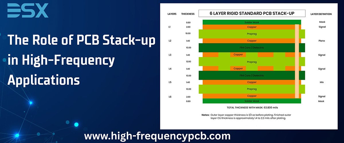
Layer Stackup Design
The arrangement of power, ground, and signal layers significantly impacts signal integrity. Industry data indicates that properly optimized stackups can reduce electromagnetic interference by up to 20dB and improve signal quality by up to 35%.
The Manufacturing Difference
While design is crucial, manufacturing execution is equally important. Here's where expertise becomes invaluable:
Precision Fabrication
High-frequency PCBs require significantly tighter tolerances than standard boards. Manufacturing capabilities must include:
· Trace width control within ±0.5 mil
· Consistent dielectric thickness (±5% variation maximum)
· Copper roughness management
· Precise drill registration
Advanced Testing Capabilities for High-Frequency PCBs
Advanced testing for high-frequency PCBs requires sophisticated equipment and methodologies beyond standard electrical testing. Vector Network Analyzers (VNAs) serve as the cornerstone of high-frequency circuit characterization, measuring S-parameters to quantify signal transmission and reflection characteristics across frequency ranges. Time Domain Reflectometry (TDR) provides critical insights into impedance discontinuities by measuring reflected signals along transmission paths. Near-field scanning systems detect EMI hotspots and radiation patterns that might compromise performance or regulatory compliance. For temperature-dependent behavior, environmental chambers combined with real-time electrical testing reveal how thermal variations affect circuit performance—essential for applications experiencing significant temperature fluctuations. Modern automated test equipment can perform in-circuit testing at high frequencies while specialized fixtures with calibrated launch points ensure measurement accuracy by minimizing the testing apparatus's influence on the circuit. Together, these capabilities enable comprehensive verification of high-frequency PCB performance parameters, ensuring designs meet stringent electrical, timing, and regulatory requirements before deployment in sensitive applications.
Traditional testing methods fall short for high-frequency boards. Time Domain Reflectometry (TDR) and Vector Network Analysis (VNA) become essential for verifying impedance characteristics and signal performance across frequency ranges.
Signal Integrity Matters in High-Frequency PCB: Use Cases
Signal integrity becomes critically important in high-frequency PCB applications for several reasons. Here are key use cases where signal integrity is essential:
High-Speed Digital Communication Systems
Data centers and telecommunications equipment require flawless signal transmission across backplanes and between boards at multi-gigabit rates. Poor signal integrity leads to increased bit error rates, making reliable communication impossible as data rates climb above 10 Gbps. Designers must carefully control impedance, minimize crosstalk, and manage reflections to maintain signal quality across transmission paths.
Wireless Communications Infrastructure
5G base stations and RF front-end modules must preserve signal fidelity for accurate modulation/demodulation. Signal degradation directly impacts receiver sensitivity and transmission power efficiency. Clean signal paths ensure proper function of low-noise amplifiers, power amplifiers, and filters operating at frequencies up to 40 GHz and beyond.
Test and Measurement Equipment
Oscilloscopes, signal generators, and spectrum analyzers require exceptional signal integrity to provide accurate measurements. Test equipment operating at high frequencies (10+ GHz) demands near-perfect transmission lines and minimal noise to maintain measurement accuracy and avoid false readings that could mislead engineers.
Radar and Electronic Warfare Systems
Military and aerospace applications rely on precise signal timing and fidelity for target acquisition and identification. Signal integrity issues can reduce detection range or create false targets. Phase-coherent systems are particularly sensitive to signal path variations that degrade system performance.
Medical Imaging Devices
MRI machines and ultrasound systems process extremely sensitive signals where noise or distortion can obscure critical diagnostic information. Signal integrity ensures accurate imaging by preserving the low-level signals from sensors and maintaining precise timing relationships.
High-Performance Computing
AI accelerators and graphics processing systems require vast amounts of data movement between processors and memory at ever-increasing speeds. Signal integrity issues can cause computational errors or require reduced clock rates, directly impacting system performance as data rates exceed 64 GT/s in modern systems.
In all these applications, maintaining signal integrity becomes more challenging and more crucial as frequencies increase. Proper design techniques, material selection, and verification testing are essential to ensure reliable system operation and avoid costly redesigns or field failures.
Why Partner with DSX Electronics?
When it comes to high-frequency PCB manufacturing, the difference between adequate and excellent is often the difference between product success and failure. According to a survey by Electronic Design magazine, 78% of engineers reported that manufacturing quality issues were the primary cause of signal integrity problems in their high-frequency designs. Our engineers team takes good care of every small details and then proceed with the final version.
Our specialized manufacturing processes at DSX have been refined specifically for high-frequency applications. With our advanced capabilities, we've helped clients:
· Reduce time-to-market by eliminating redesign cycles
· Achieve first-pass success rates exceeding 95%
· Meet or exceed performance specifications consistently
· Improve product reliability and reduce warranty claims
Taking the Next Step
Signal integrity isn't just a technical consideration—it's a competitive advantage. As frequencies continue to increase and designs become more complex, working with a manufacturing partner who truly understands high-frequency PCB challenges becomes increasingly critical.
Our team of expert engineers is ready to review your design requirements and provide insights that can make the difference between marginal performance and exceptional results. From material selection to impedance control strategies, we provide comprehensive support throughout your product development process.
Don't let signal integrity issues delay your next project or compromise your product's performance. Contact us today to discuss how our specialized high-frequency PCB manufacturing capabilities can help you achieve the signal integrity your application demands.
 The Role of PCB Stack-up in Hi
 Why Are High-Frequency PCBs Es
 High-Frequency PCB vs. RF PCB:
Why Signal Integrity Matters i
High-Frequency PCB vs. RF PCB:
Why Signal Integrity Matters i